j'ai trouvé ça mais dur de déchiffrer correctement

4.13 Check fuses F114 and F115 message
This message is sometimes displayed when the game boots and a game cannot be started. Most of the time, F114/F115 will be found to be just fine.
The game issues this message because it cannot read the switch matrix normally. The crafty designers at Williams inserted an “always closed“ switch into the matrix as switch 24. Switch 24 isn’t a switch at all, but instead provides the game software with a “known closed” switch matrix return. Switch 24 is actually a diode across column 2, row 4 of the switch matrix and is located on the coin door interface board.
Since the WPC switch matrix circuitry on the MPU uses 12V to determine switch state, the game assumes that the 12VDC power has been interrupted. F114/F115 fuse the 12V generation circuit; F114 on the AC side of BR1; F115 on the DC side of BR1. Hence, the game assumes that one of these fuses is blown and the message is displayed.
Diagnosing the problem
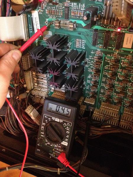
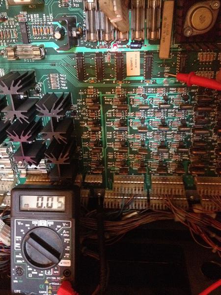
Start by checking DC voltage at TP3. You should see about 12VDC. If not, follow these steps.
Actually check fuses F114 and F115 using the procedure here. If a blown fuse is found, replace it. If F114 immediately blows again, then BR1 is probably shorted. Skip to the paragraph below to test the bridge.
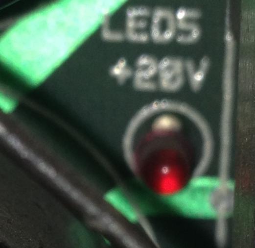
Check LED6. If not lit (indicating the absence of 18V at TP8), then suspect BR1 or the filter caps for BR1, C6 and C7. If BR1 had failed shorted or if C6 or C7 where shorted (rare) then you would expect to see F114 blown. BR1 can be tested using the procedure below.
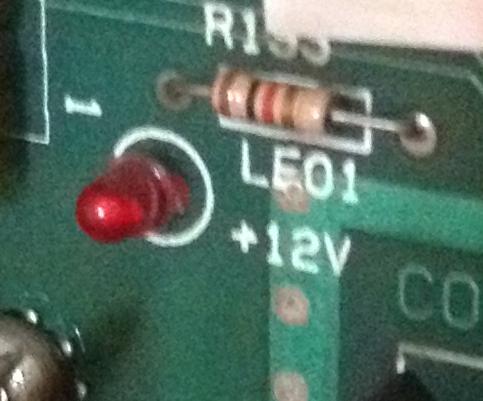
Check LED1. If not lit (indicating the absence of “digital” 12V at TP3, then test D1 and D2 (both 1N4004 diodes). If D1/D2 test good, then check continuity from pin 2 of the 7812 voltage regulator at Q2 to J114, pin 1. This verifies the path through F115.
If this all checks out, yet 12VDC is still not at TP3, then suspect the 7812 voltage regulator at Q2. Q2 is in a TO-220 package (like a TIP-102) and has a small heat sink attached.
There is one more way for the 12VDC power to be lost. A shorted IC on the MPU that uses 12VDC can cause F115 to blow. To help isolate the problem to the MPU, replace F115, disconnect power going to the MPU at J210, and turn power to the game on. If the fuse does not blow, the problem is almost definitely on the MPU board. Any of the LM339s (theoretically) or the ULN2803 (definitely) can fail and short 12V to ground, causing F115 to blow.
")